
Nasumil Enterprise and Technology limited offers a comprehensive range of varies hydropower plant equipment such as Turbine, Generator, excitation and power Transformer solutions. As hydropower plants consist of electrical and mechanical components in which Mechanical components include gates, turbine, gearbox, tanks, piping and hydraulic power unit where by electrical components include generator, automatic voltage regulator, transformer, and transmission line. Nasumil Enterprise and Technology limited offers equipment in both categories of hydro power plant.
Main inlet valve (MIV) works as the isolating valve in the water conductor system. It is located before turbine and allows water flow from penstock to turbine. MIV is used as a safety device in the hydropower plant. MIV acts as closing valve and cuts the flow of water during an emergency trip. Controls the flow of water into the turbine. Nasumil Enterprise and Technology limited offers all equipment which covers the whole range as follows:
- Servomotor
- Bypass valve
- Position sensor
- Pressure pump
- Directional valve
Is a self-contained system that includes a motor, a fluid reservoir, and a pump. These components work together to generate hydraulic energy, which is then used to power various types of machinery and equipment. The HPU converts mechanical energy into hydraulic energy, allowing for precise control of movements and forces in hydraulic systems. The fluid, typically oil, is pressurized by the pump and then directed through valves to the actuators, such as cylinders or motors, which perform the desired work. Provides hydraulic pressure for controlling valves and other equipment.
- Ops pump
- Hydraulic oil
- Direction valve
- Proportion valve
- Pressure transmitter
- Pressure sensor
Is to maintain a constant speed in response to variation in load. The governor is a part of the turbine control system that controls rotational speed in response to changing load circumstances. The governor varies the water flow through the turbine to control its speed or power output.
- Speed sensor device
- Limit switch
- Displacement sensor
- Pressure switch
- Proportional valve
- Magnetic level sensor
- Water detector sensor
- Temperature transmitter
- Analogue meter
- Temperature sensor
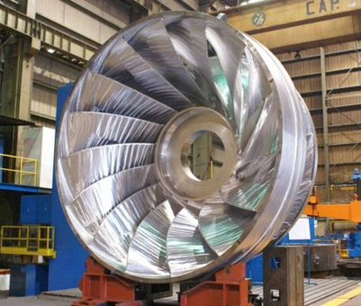
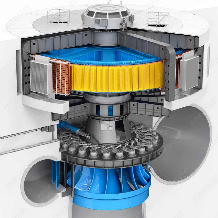
Produce nearly all of the electric power for worldwide electric power grids.
- Generator neutral ground
- Generator Heat exchange
- Brake pad
- Limit switch
- Hydraulic and pneumatic valves
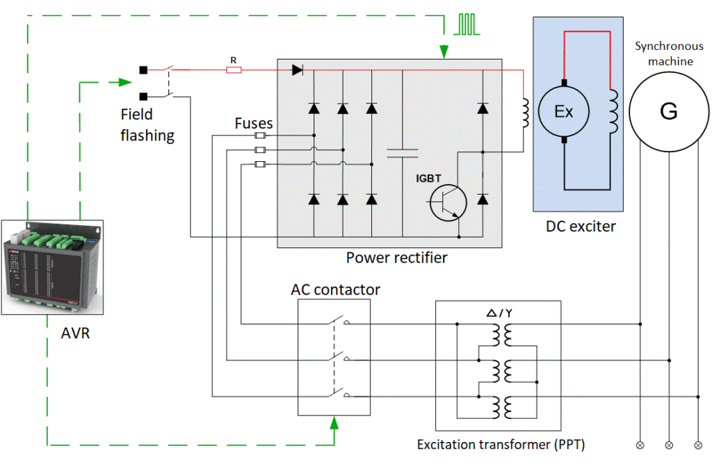
Provides the magnetic field needed for the generator to produce electricity.
- Carbon brush and holder
- Extract fan /carbon dust collector
- Field breaker
- Field flash contactor
- AVR
- Silicon controlled rectifier
- Discharge resistor
- Braking system
As usual Nasumil Enterprise and Technology limited always prefers to elaborate the general ideas in its various lines of business for overview knowledge for the benefit of those who will come across the line.
Hydropower is one of the oldest and largest energy sources for producing electrical energy. Hydroelectric power plants generate approximately 16% of all electricity worldwide. The volume of the water flow and the change in elevation, often referred to as head from one point to another, determine the potential energy in moving water. Generally, the greater the water flow and the higher the head, the more electricity a hydroelectric power plant can produce.
Hydroelectric power plants can be categorized as two by means of energy-generating methods:
- Storage systems
- un-of-the-river
Storage systems, where water accumulates in reservoirs created by dams on water streams and rivers and is released through hydroelectric turbines as needed to generate electricity.
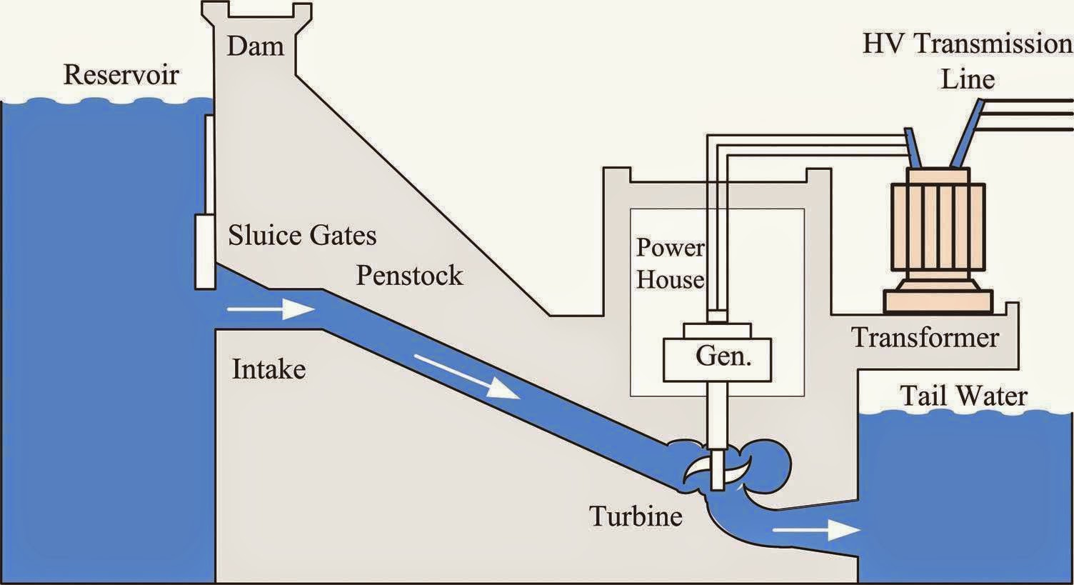
A run-of-the-river type plant is a facility that channels the flowing water from a river through a canal or penstock to spin a turbine. Generally, these plants have no or very limited water storage facility compared to dams.
Turbines, generators, powerhouses and transformers are common equipment for both storage and run-of-the-river applications. The difference between run-of-the-river compared to storage types is that they primarily use the natural flow rate of water to generate power instead of the power of the water falling a large distance.
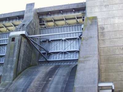
Radial (sluice) gates are electromechanical units used in dams and canal locks to control water flow. They are used to transfer water to turbine units and are also used to discharge excess water. Typically, hydraulic systems are used to open and close the gates.
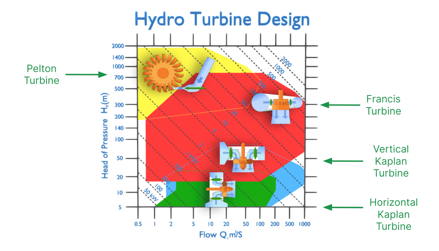
The most commonly used turbines are Kaplan, Francis, and Pelton. The type of hydropower turbine selected for a project is generally based on head, flow rate at the site, how deep the turbine is installed, turbine efficiency, and cost.
The Kaplan turbine is a type of reaction turbine, both the runner blades (propeller) and the wicket gates are adjustable, allowing for a wider range of production control. They are efficient for low head / high flow applications. Kaplan turbines rotate at a constant speed ranging from 50 to 450 rounds per minute.
The Francis turbine is also a reaction turbine, usually having nine or more fixed runner blades. They are also equipped with wicket gates to control the operation and are commonly used for medium to high head/medium flow applications.
The Pelton turbine is an impulse type of turbine where these turbines generally use the velocity of the water to move the runner and discharge at atmospheric pressure. Pelton turbines are usually used for very high heads and low flows.
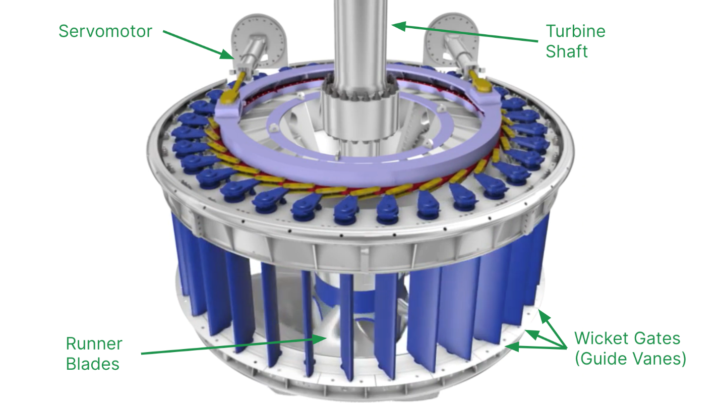
A critical component of Kaplan and Francis turbines, Wicket gates allow water to flow into the runner chamber. The primary function of wicket gates is to change the angle as per the requirement to control the angle of striking of water to runner blades to increase the production efficiency. They also regulate (with the help of adjustable guide vanes) the flow rate of water into the runner blades, thus controlling the power output of a turbine according to the load on the turbine. The regulating mechanism of the wicket gates consists of servo motors and a hydraulic governor, which controls the angle of the guide vanes.
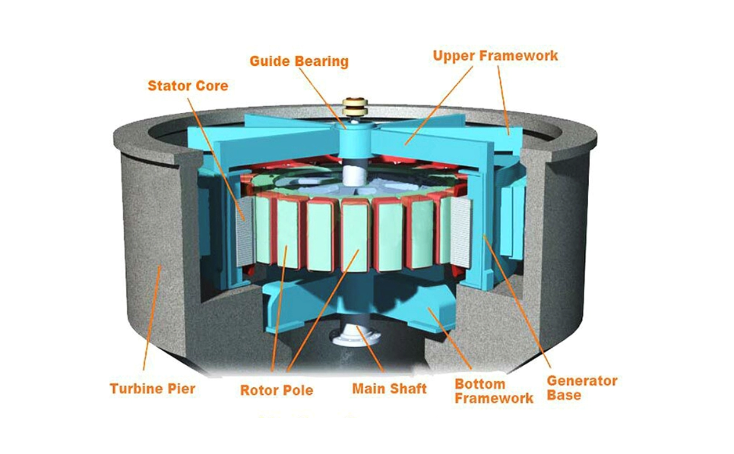
A typical generator consists of a rotating part (rotor) and a stationary part (stator) that surrounds the rotating part. Hydroelectric generators convert flowing water’s mechanical energy into electricity. The rotor is attached to the main shaft and rotates at the speed of the turbine or the gearbox. In a generator, electromagnets are made by circulating direct current through field poles, which are mounted on the perimeter of the rotor. During the rotation, it causes the field poles (the electromagnets) to move past the conductors mounted in the stator. This leads electricity to flow and a voltage to develop at the generator output terminals, which is then transferred to the transformers.
Thank you for having NASUMIL ENTERPRISE AND TECHNOLOGY LIMITED, beyond boundaries, beyond limits.